
Industrial patent case studies
Case Studies | Industrial Patents for Businesses
Industrial Patent for P.A.L. Italia Srl
Sector: Rail and tram transport technologies
Client: P.A.L. Italia Srl (https://www.palitalia.net/)
The invention
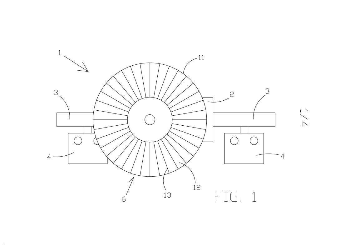
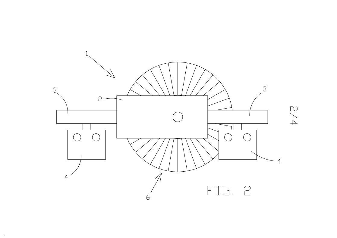
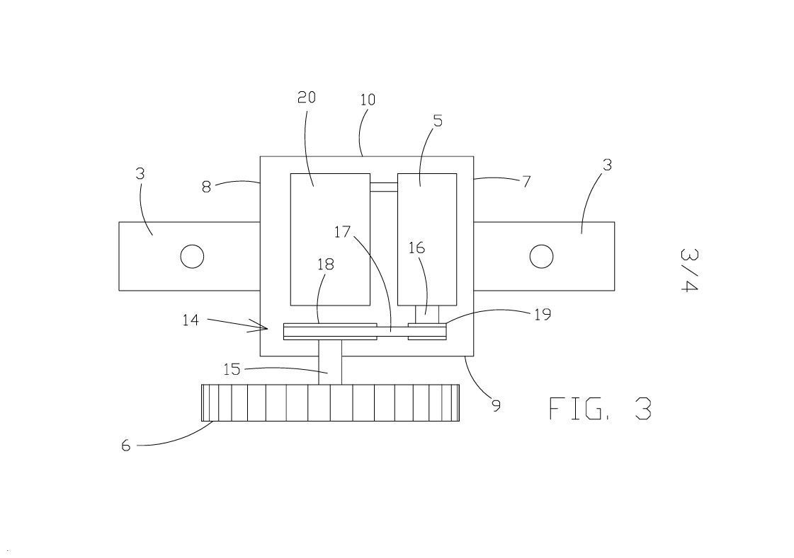
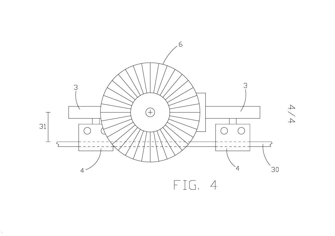
A device for detecting the passage of an electric rail vehicle on a railway/tramway network through interaction between the pantograph and the electrified overhead line. It powers itself using an integrated dynamo and transmits detection signals via radio frequency.
The problem addressed
In rail and tram transport, the rails need to be lubricated to minimize friction between them and the wheels of rail vehicles. Lubrication frequency depends on how often vehicles pass, and current systems require wired sensors, making installation complex.
Benefits of the invention
The device is activated only when a rail vehicle passes, powering itself through contact between the pantograph and the electrified line. It requires no power or transmission cables, making it easy to install and precise in detecting vehicles.
Technical images relating to the PAL Italia Srl case:
Industrial Patent – OMEV S.n.c. di Virginio & Figli
Sector: Technologies for manufacturing baking trays for bakeries and industrial breadstick producers
Client: OMEV S.n.c. di Virginio & Figli ( https://www.omevsnc.com/ )
The invention
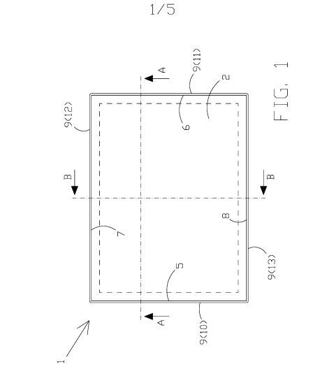
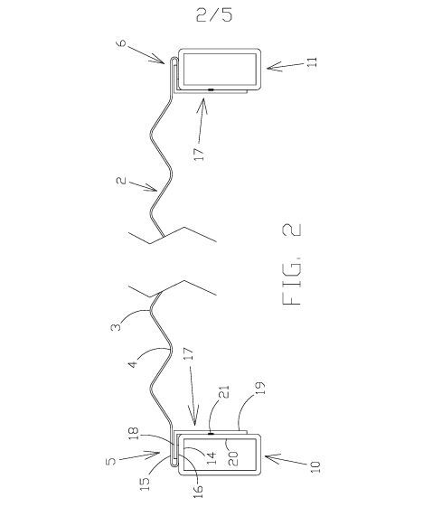
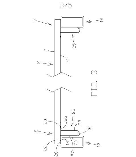
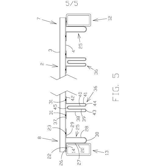
The invention relates to an oven tray for baking breadsticks, comprising a corrugated sheet connected to a tubular perimeter frame substantially shaped like a rectangular border. The connection between the sheet and the frame allows at least partial compensation for differences in thermal expansion between them. More specifically, the sheet edges parallel to the direction in which its ridges and grooves extend are connected to the opposing tubular frame members by folding the sheet back on itself in a U-shape at those edges and fitting them over respective L-shaped profiles suitably connected to the tubular frame members by resistance spot welding. The sheet edges perpendicular to the direction in which its ridges and grooves extend are connected to the opposing tubular frame members by respective Ʊ-shaped profiles, with the two arms of each Ʊ connected to the frame member and the sheet, respectively, by resistance spot welding. The frame may also include additional ω-shaped reinforcing profiles, with both ends of each ω connected to the sheet by resistance spot welding.
The problem addressed
Current oven trays for baking breadsticks comprise a corrugated steel sheet rigidly connected by resistance spot welding to a tubular perimeter frame substantially shaped like a rectangular border and also made of steel.
When the tray becomes significantly hotter, for example when placed in an oven, the steel it is made of expands. However, the sheet and the frame expand at different rates because of their different masses and geometries. The differences in thermal expansion between the sheet and the frame cause relatively high stresses at the weld points. Since these points are extremely rigid, the differences in thermal expansion distort the tray unevenly, eventually causing one or more weld points to fail (and the sheet to become at least partly detached from the frame) or the sheet to crack.
One proposed solution has been to connect the sheet and the frame with rivets rather than welds. Although rivets partially compensate for differences in thermal expansion between the sheet and the frame, they tend to loosen and detach from the sheet, potentially contaminating the breadsticks being baked on the tray.
Advantages of the invention
In the tray of the invention, the connection between the sheet and the frame allows both components to expand thermally without generating stresses that could, through use of the tray, cause the sheet to detach from the frame or crack. A further advantage of the tray is that its first and second bars act as ribs, making it possible to reduce the cross-section of the tubular frame members while maintaining the same stiffness.
Technical images relating to the case OMEV S.n.c. di Virginio & Figli :
Industrial Patent for Veronica Vico
Sector: Accessories and equipment for machine tool worktables
Client: Veronica Vico
The invention
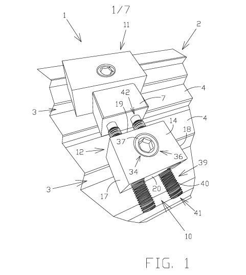
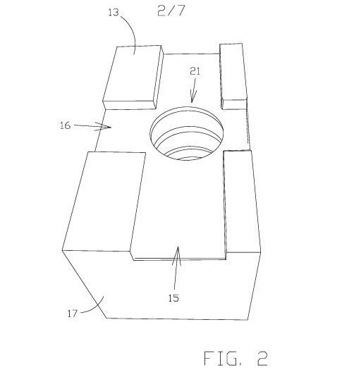
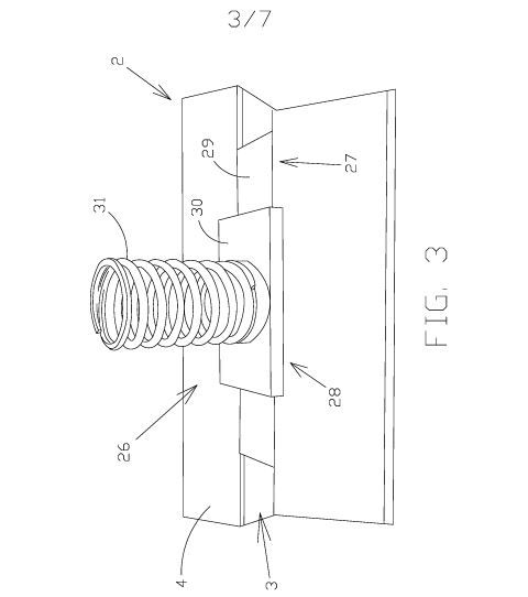
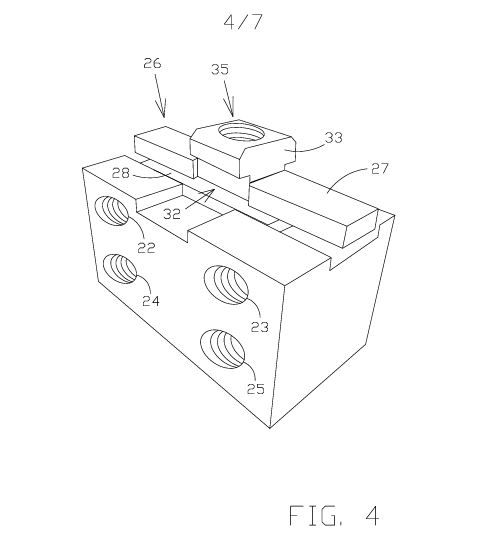
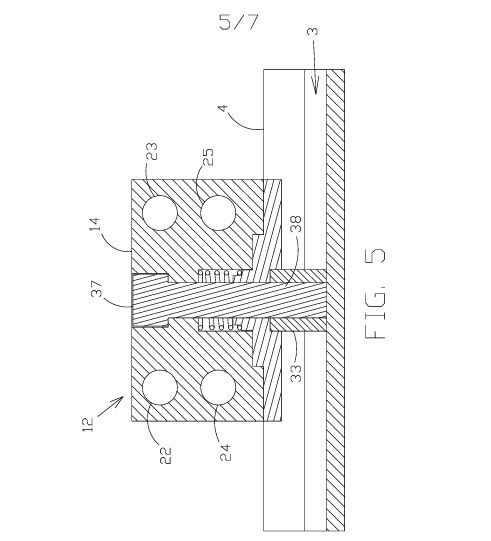
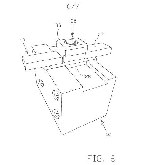
The invention is a vice comprising two or more jaws that can be reversibly connected to the worktable of a machine tool independently of one another. More specifically, each jaw comprises a preferably metal block that can be connected to a worktable by clamping the block to the table with a bolt whose clamping element is housed in a groove in the table. Of the jaws of the vice in this invention, those acting as movable jaws are fitted with a screw housed in a threaded through-hole in the corresponding block and movable relative to the block when the screw is rotated around its longitudinal axis.
The problem addressed
Conventional machine vices generally comprise a base that can be fixed and reversibly connected to a machine tool’s worktable by means of one or more fastening bolts and suitable through-holes in the vice base. As is well known, the worktable of a machine tool has a series of straight, mutually parallel grooves, preferably all of the same size and equally spaced. Each groove extends from one edge of the table to the opposite edge and generally has a substantially inverted T-shaped cross-section. As a result, each groove is accessible from the face of the table in which it is formed, at the part corresponding to the stem of the T in its cross-section (with the stem preferably perpendicular to that face). Each groove is also accessible at both edges of the table where the groove begins and ends, at its cross-section. Each groove serves as a housing and sliding track for the nuts of the aforementioned fastening bolts. In particular, the nut of each fastening bolt can be housed in any groove in the part corresponding to the head of the T in the groove’s cross-section—that is, in the part of the T perpendicular to its stem and extending to either side of it. When housed in a groove in the worktable as described above, the nut of each fastening bolt is positioned so that its threaded hole is accessible from the part of the groove corresponding to the stem of the T in its cross-section. Each fastening bolt nut, like each groove, is shaped so that, when housed in a groove as described above, the nut can slide along the groove without rotating relative to it or coming out through the part corresponding to the stem of the T in its cross-section. A fastening bolt nut can therefore be inserted into and removed from a groove in a machine tool’s worktable only at the table edges where the groove begins and ends.
Once the base of a machine vice has been placed in the desired position on a machine tool’s worktable, connecting it securely and reversibly to the table requires first inserting a fastening bolt nut into one of the table grooves and sliding it along the groove until its threaded hole aligns with one of the aforementioned through-holes in the vice base. The bolt screw is then inserted through that hole in the vice base so that, after passing through the base, its shank enters the groove through the part corresponding to the stem of the T in its cross-section, with the screw head on the opposite side of the vice base from the table (that is, with the screw head and the table on opposite sides of the vice base). The head of each fastening bolt screw is sized so that it cannot pass through any of the through-holes in the vice base. The shank of each fastening bolt screw is also long enough to reach the threaded hole of a bolt nut housed in a table groove and aligned with the through-hole in the vice base. To connect the vice base to the machine tool’s worktable, it is therefore only necessary to screw the shank of the fastening bolt through the vice base into the threaded hole of the nut (housed in a worktable groove) far enough to clamp the vice base between the screw head and the table. This clamping action, repeated as needed with other fastening bolts whose shanks are inserted through other holes in the vice base, secures the vice base to the machine tool’s worktable by friction.
In addition to the base, each machine vice generally comprises a pair of jaws that can move towards and away from one another, with at least one jaw also movable relative to the vice base. Generally, one jaw is fixed to the vice base and the other moves relative to it by means of a lead screw.
As noted above, the size and shape of a workpiece that can be clamped between the jaws of a conventional machine vice are partly constrained by the design, and especially the dimensions, of the vice base.
Advantages of the invention
In the vice described in this invention, the jaws can be connected directly to the worktable of a machine tool independently of one another. This makes it possible to reversibly secure a much wider range of workpieces, in terms of both shape and size, to a machine tool’s worktable than with a conventional machine vice. The vice in this invention can be adapted, at least in part, to the workpiece being clamped (that is, to its shape and dimensions).
Technical images relating to the Veronica VIco case:
Utility Model for STS Italia S.r.l.
Sector: Process control instrumentation
Client: Sts Italia S.r.l.
Subject matter of the utility model
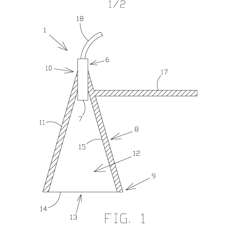
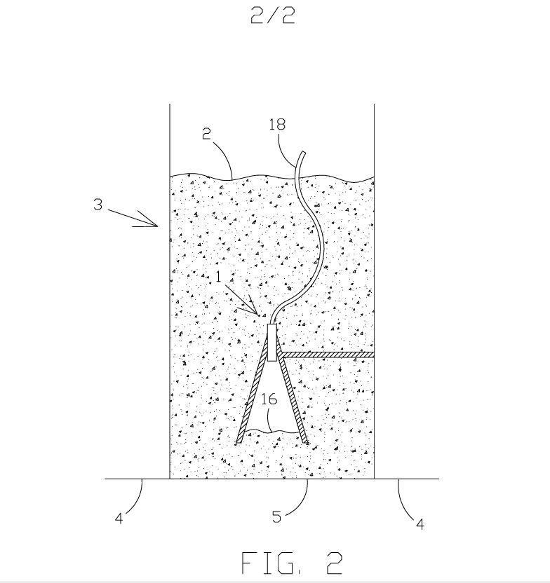
The utility model relates to an apparatus for determining the level of liquid in a vessel. The apparatus comprises a preferably frustoconical container, open at its larger base and rigidly connected at its smaller base to a diaphragm pressure sensor. The sensor is connected to the container so that the diaphragm is housed inside it. When the container is immersed in a liquid whose level is to be determined, the liquid closes the container opening, trapping a gaseous fluid, preferably atmospheric air, inside. The sensor measures the pressure of this fluid, which corresponds to the liquid pressure at the interface between the gaseous fluid and the liquid inside the container. A suitable processing unit uses the pressure measured by the sensor and the known immersion depth of the container to determine the hydrostatic head at the aforementioned interface and, consequently, the liquid level in the vessel. The apparatus covered by the utility model is therefore a hydrostatic head level meter that uses a gaseous working fluid to indirectly measure, at a given depth, the pressure of the liquid whose level is to be determined.
The problem addressed
Current hydrostatic head apparatus for determining the level of liquid in a vessel generally include very delicate diaphragm pressure sensors. The measuring diaphragm in these sensors is extremely thin, making the sensor’s actual sensing element very fragile. To protect the sensor diaphragm from impacts with objects that may be present in the liquid whose level is being measured, current immersion apparatus includes a kind of cage enclosing the sensor diaphragm. Its mesh is wide enough to let the liquid reach the diaphragm while preventing objects of a certain size from passing through the cage (and consequently coming into unwanted contact with the diaphragm). Over time, however, debris in the liquid whose level is being measured can accumulate in the mesh and block the cage. If this happens, the apparatus sensor can no longer measure the pressure and, consequently, determine the liquid level.
Advantages of the invention
The patented sensor can measure the pressure exerted by the liquid at a specific point inside the vessel, referred to as the “liquid pickup point”. Using the pressure measured by the sensor and knowing the specific gravity of the liquid whose level is being measured, the control system can calculate the hydrostatic head at that pickup point—that is, the depth of the pickup point below the free surface of the liquid in the vessel (the distance between the pickup point and the liquid surface). It can also calculate the liquid level in the vessel relative to a reference plane by adding the hydrostatic head to the known elevation of the pickup point relative to that plane.
Technical images relating to the case STS Italia S.r.l.:
Industrial Patent for Stelar S.r.l.
Sector: Components for high-field electromagnets
Client: Stelar S.r.l.
The invention
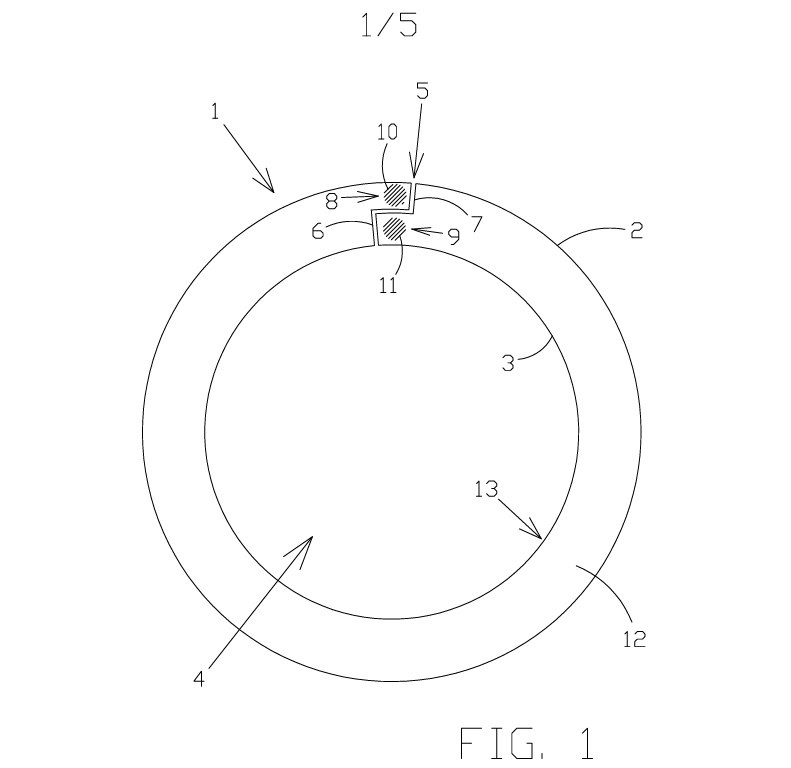
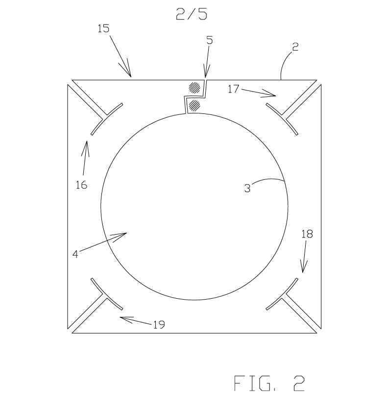
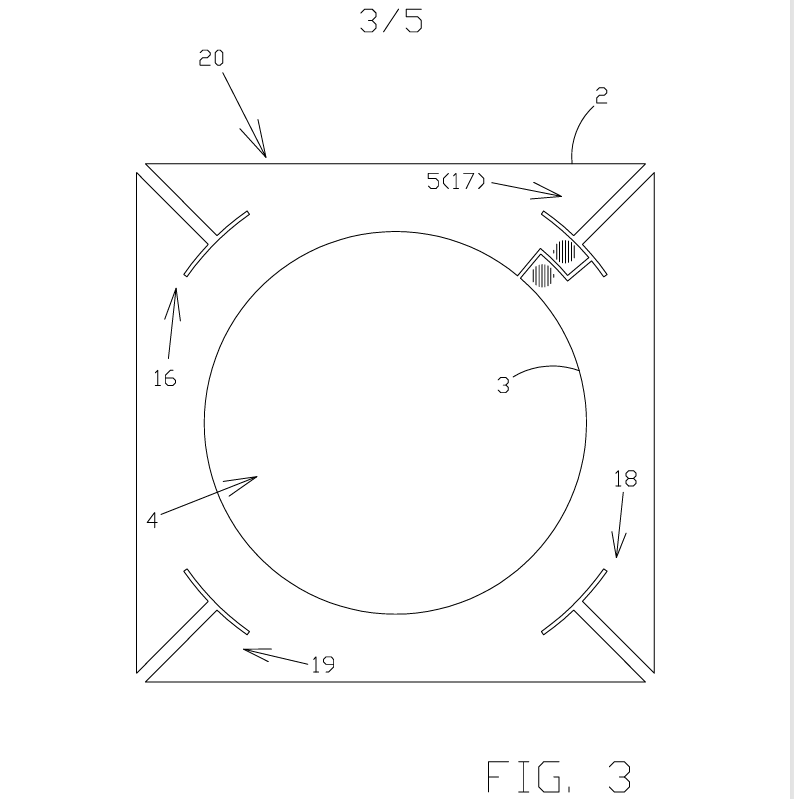
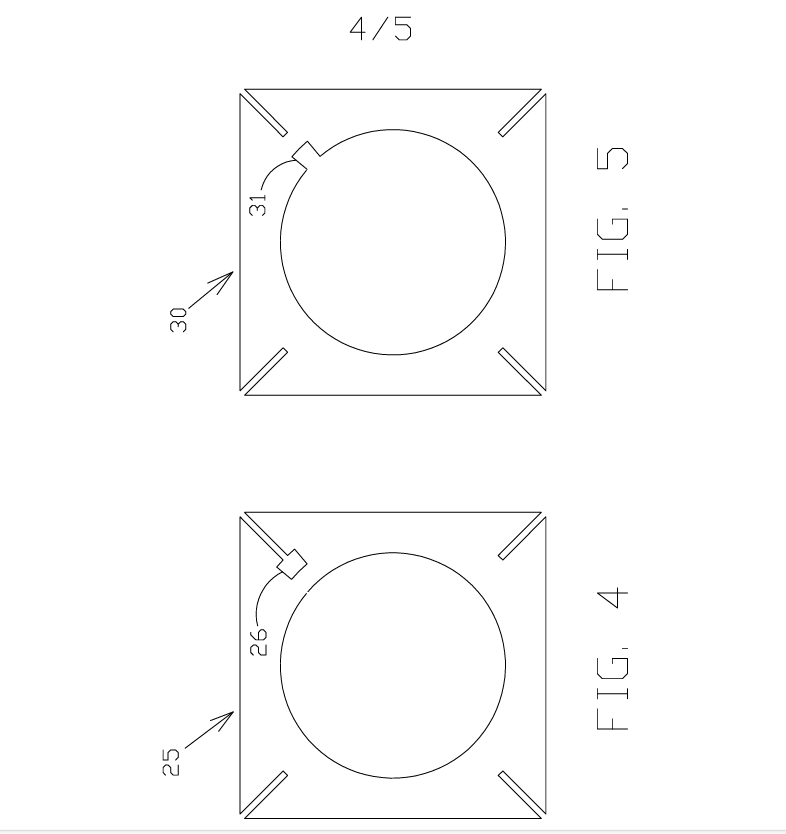
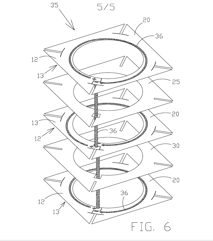
The invention relates to a preferably metal plate that can be incorporated as a conductive plate in a Bitter electromagnet or solenoid. Unlike in the prior art, the slot through the plate does not extend only radially, but instead defines two recesses positioned one above the other in the radial direction. The electrical connection between the plate and the two adjacent plates occurs at these recesses when a Bitter electromagnet or solenoid is assembled. The latter can therefore be made using conductive plates that are identical to one another and simply rotated in opposite directions about a diameter in the stack that makes up the Bitter electromagnet or solenoid. The invention also relates to a Bitter electromagnet or solenoid comprising the plate described above.
Problem addressed
Current Bitter electromagnets or solenoids comprise multiple electrically conductive plates facing one another, with an electrically insulating plate between each pair of immediately adjacent conductive plates. The conductive plates and insulating plates are preferably identical to one another, and each is preferably shaped like an annular ring with a radial slot, preferably corresponding to a circular sector of the ring. The slots in the conductive plates are generally narrower in angular extent than those in the insulating plates. In known Bitter electromagnets or solenoids, the conductive plates face one another, with insulating plates between them, so that their radial slots (that is, those in the conductive plates) follow a helical path. Each insulating plate is also positioned between a pair of conductive plates so that its radial slot lies substantially between the radial slots in the two conductive plates of that pair. Accordingly, in known Bitter electromagnets or solenoids, the insulating plates also face one another, with conductive plates between them, so that their radial slots (that is, those in the insulating plates) follow a helical path.
Advantages of the invention
The plate of the invention can be used to build a Bitter electromagnet or solenoid (with the plate incorporated into it) without having to ensure that the conductive plates face one another (with insulating plates between them, or with electrical insulation created between them) so that their radial slots (that is, those in the conductive plates) follow a helical path, and that any insulating plates face one another, with conductive plates between them, so that their radial slots (that is, those in the insulating plates) follow a helical path. More specifically, a Bitter electromagnet or solenoid can be made simply by stacking multiple plates according to the invention (with an electrically insulating plate between each pair of immediately adjacent conductive plates, or with electrical insulation created between them) so that each pair of immediately adjacent plates face one another on the same (first or second) face, with their first portions at least partially aligned with one another and their second portions at least partially aligned with one another. In a Bitter electromagnet or solenoid comprising multiple plates according to the invention, electrical contact between one of the plates of the invention and the two adjacent plates between which it is positioned (that is, the immediately preceding and immediately following plates in the stack) occurs at the aforementioned first and second portions.
Since the plates of the invention no longer need to be stacked in a helical arrangement to make a Bitter electromagnet or solenoid, they no longer have to be shaped like annular rings. This is a significant advantage: plates of any shape can be stacked, making it possible to choose a shape that suits the desired electrical properties of the plate and/or the desired shape of the electromagnet or solenoid.
Technical images relating to the case Stelar S.r.l.:
Industrial Patent for Wind Technologies S.r.l.
Field: Wind turbine with vertical axis for converting wind energy into electrical energy
Client: Wind Technologies S.r.l.
The invention
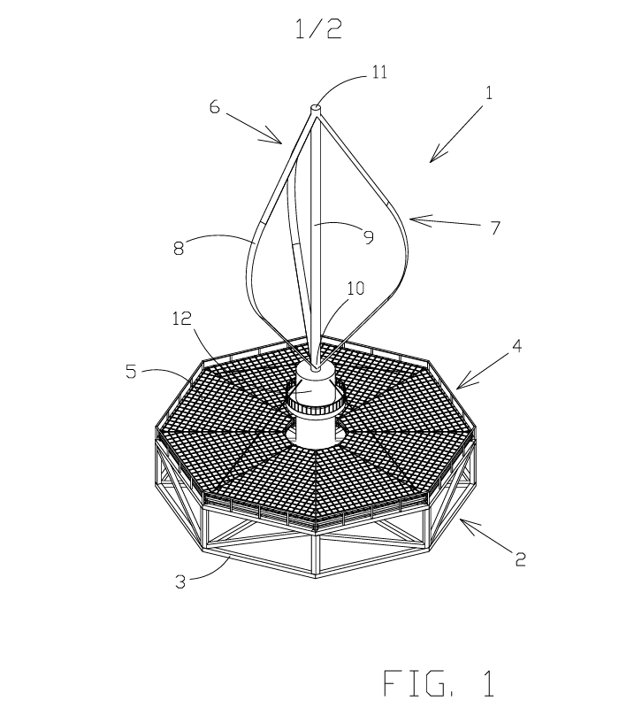
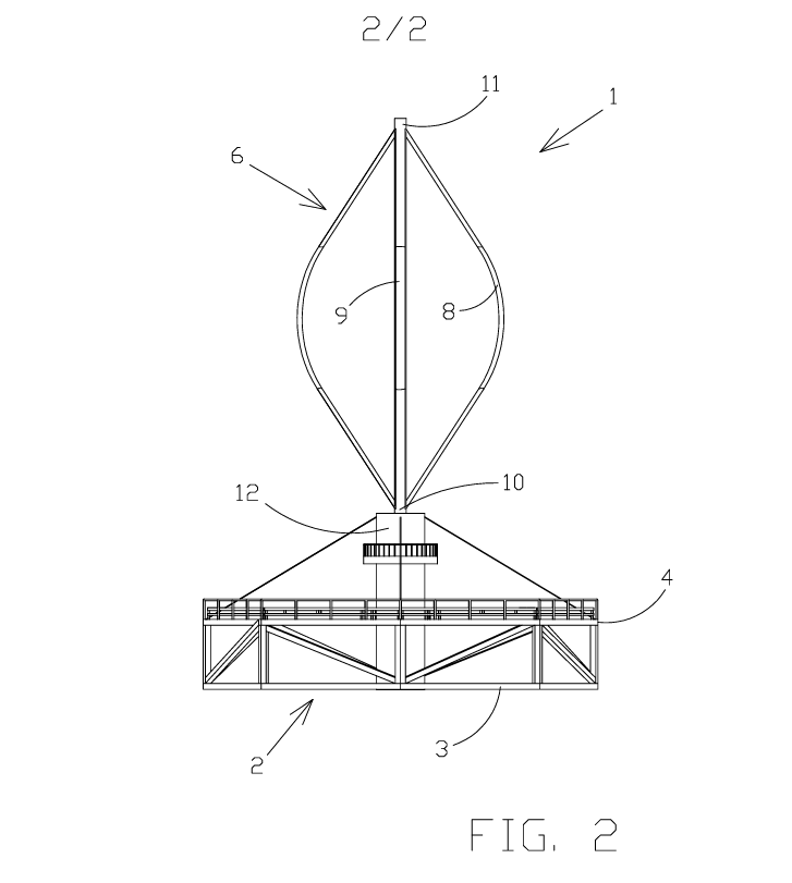
The invention relates to a floating offshore platform for converting wind energy into electrical energy using a Darrieus-type vertical-axis wind turbine, and solar energy into electrical energy using a number of photovoltaic modules that also supply the electricity needed to start the turbine.
The problem addressed
Current wind turbines installed on offshore platforms are horizontal-axis turbines—that is, turbines with blades that rotate around a horizontal axis under the force of the wind. As is well known, these turbines can convert wind energy into mechanical energy only when the rotor is oriented in the direction of the wind. Therefore, for a horizontal-axis wind turbine to operate whenever there is wind, the rotor must be kept facing the wind. However, winds at sea repeatedly change direction. For a horizontal-axis wind turbine installed on an offshore platform to operate whenever there is wind, the rotor must therefore be repeatedly turned to keep it facing the wind.
Advantages of the invention
Unlike a horizontal-axis turbine, a vertical-axis turbine can convert wind energy into mechanical energy regardless of the direction of the wind. The turbine on the platform covered by the invention can “accept” wind from any direction. In addition, unlike horizontal-axis wind turbines, it does not need blade pitch control mechanisms or a gearbox. Having fewer moving parts has the advantage of reducing wear compared with horizontal-axis wind turbines.
Technical images relating to the case Stelar S.r.l.:
BREVETTI DIGIOVANNI SCHMIEDT
Have an industrial invention you need to protect?
Turn to the industrial property consultants at Brevetti Digiovanni Schmiedt to turn your idea into a legally registered patent.
+39 02 29514249